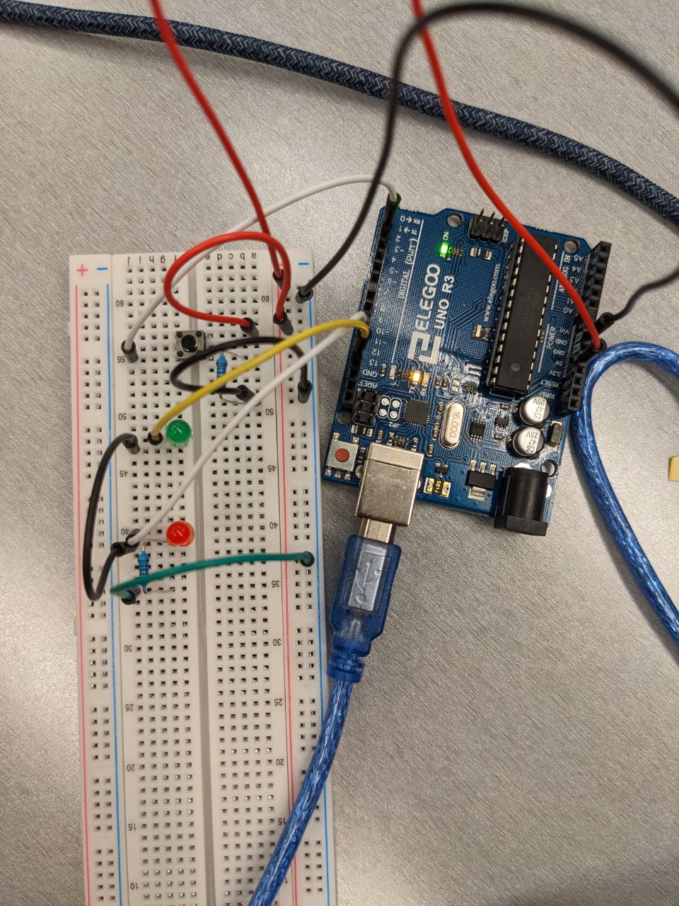
Schematic


The images above are my schematic for assignment 2. There are 2 LEDs, their positive nodes are connected to pin 13 and 11 of the Arduino. Their negative nodes are connected together and connected with a 1000 ohm resistors in series. Then the resistor is connected to the ground on the Arduino board. There's also a button which have one side connected to a 5V power source and pin 2 of the Arduino, and the other side connected to a 1k resistor, which then connects to the ground.
Why 1K?
From data sheet we know that LED have a working current of 20mA. When Arduino's pins are acting as power, they provide 5V power.
From the equation I = V / R, we can calculate that a 250 ohm resistor is needed as a bare minimum. In order to limit the current and make the LEDs safer,
I chose a 1k resistor for the LEDs.
How to Detect Button Press?
From the schematic we know that the button has one side connected to a 5V source, and the other side connected to a resistor, then to the ground. When the button is depressed, current flows from the source to the ground, resulting in voltage different between the resistor, so the button also have a voltage drop of 5V from ground. When the button is released, no current flows, so no voltage drops between the resistor, so there's no voltage drop from the button to ground. Pin 2 of the Arduino acts as a voltage meter, so it can measure the voltage drop from the button to the ground to see if it's depressed.
A Lighting Equation
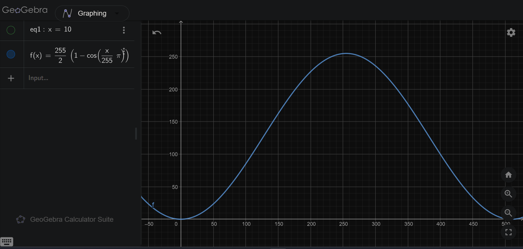
When testing the code, I found that the value of analogWrite is not a linear relationship with the brightness of the LED. When analogWrite increases constantly, the LED's brightness would grow fast at first and then slow down.
Using the functions in the Arduino library, I developed a function that can produce a shifted cosine wave that have an input field and a output field both from 0 to 255. The screenshot below shows the graph of the function.
f(x) = 255 / 2 * (1 - cos(x * PI / 255))