#include <SPI.h>
#include <Wire.h>
#include <Adafruit_GFX.h>
#include <Adafruit_SSD1306.h>
#include <Encoder.h>
#define SCREEN_WIDTH 128 // OLED display width, in pixels
#define SCREEN_HEIGHT 64 // OLED display height, in pixels
// Declaration for an SSD1306 display connected to I2C (SDA, SCL pins)
#define OLED_RESET -1 // Reset pin # (or -1 if sharing Arduino reset pin)
Adafruit_SSD1306 display(SCREEN_WIDTH, SCREEN_HEIGHT, &Wire, OLED_RESET);
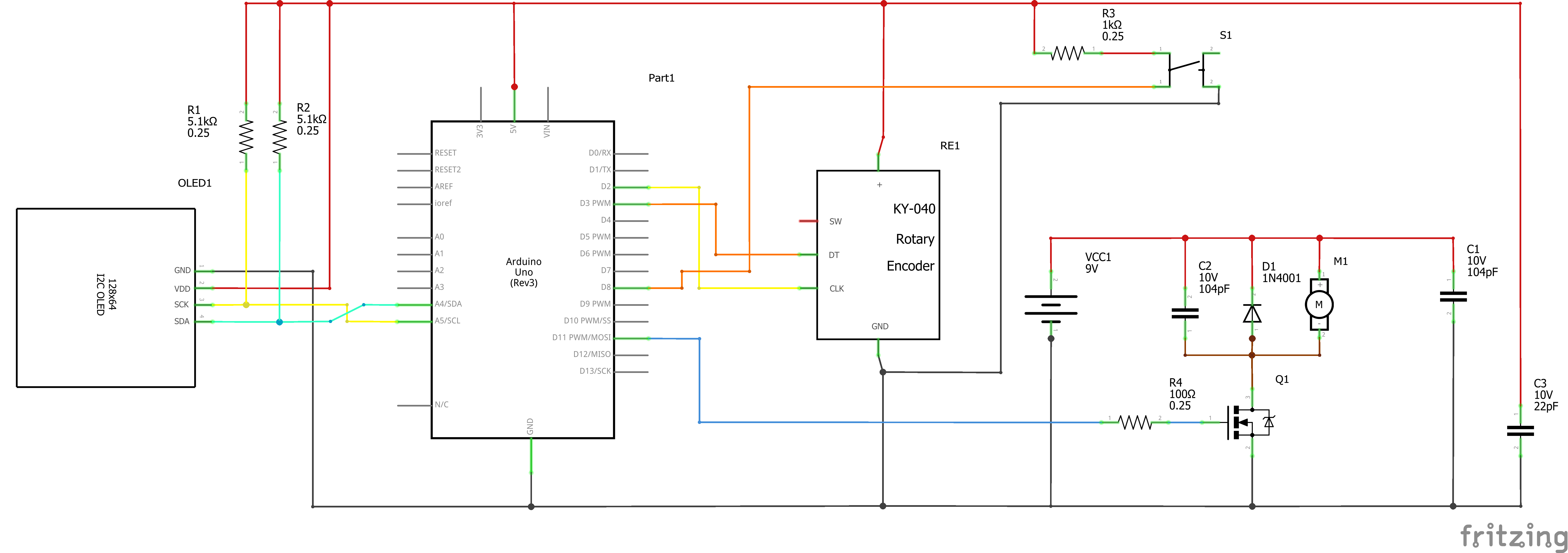
#define SW_PIN 8 // Encoder Switch pin to 8
// A Mitsubishi Logo to display
// 'images', 48x48px
const unsigned char epd_bitmap_images [] PROGMEM = {
0x00, 0x00, 0x00, 0x00, 0x00, 0x00, 0x00, 0x00, 0x00, 0x00, 0x00, 0x00, 0x00, 0x00, 0x00, 0x00,
0x00, 0x00, 0x00, 0x00, 0x00, 0x00, 0x00, 0x00, 0x00, 0x00, 0x01, 0x80, 0x00, 0x00, 0x00, 0x00,
0x01, 0x80, 0x00, 0x00, 0x00, 0x00, 0x03, 0xc0, 0x00, 0x00, 0x00, 0x00, 0x03, 0xc0, 0x00, 0x00,
0x00, 0x00, 0x07, 0xe0, 0x00, 0x00, 0x00, 0x00, 0x0f, 0xe0, 0x00, 0x00, 0x00, 0x00, 0x0f, 0xf0,
0x00, 0x00, 0x00, 0x00, 0x1f, 0xf8, 0x00, 0x00, 0x00, 0x00, 0x1f, 0xf8, 0x00, 0x00, 0x00, 0x00,
0x3f, 0xfc, 0x00, 0x00, 0x00, 0x00, 0x7f, 0xfc, 0x00, 0x00, 0x00, 0x00, 0x7f, 0xfe, 0x00, 0x00,
0x00, 0x00, 0xff, 0xfe, 0x00, 0x00, 0x00, 0x00, 0xff, 0xff, 0x00, 0x00, 0x00, 0x00, 0x7f, 0xfe,
0x00, 0x00, 0x00, 0x00, 0x7f, 0xfe, 0x00, 0x00, 0x00, 0x00, 0x3f, 0xfc, 0x00, 0x00, 0x00, 0x00,
0x3f, 0xf8, 0x00, 0x00, 0x00, 0x00, 0x1f, 0xf8, 0x00, 0x00, 0x00, 0x00, 0x1f, 0xf0, 0x00, 0x00,
0x00, 0x00, 0x0f, 0xf0, 0x00, 0x00, 0x00, 0x00, 0x07, 0xe0, 0x00, 0x00, 0x00, 0x00, 0x07, 0xc0,
0x00, 0x00, 0x00, 0x00, 0x03, 0xc0, 0x00, 0x00, 0x00, 0x00, 0x03, 0x80, 0x00, 0x00, 0x00, 0x00,
0x01, 0x80, 0x00, 0x00, 0x00, 0x00, 0x00, 0x00, 0x00, 0x00, 0x00, 0xff, 0xfe, 0xff, 0xff, 0x00,
0x01, 0xff, 0xfe, 0x7f, 0xff, 0x00, 0x01, 0xff, 0xfc, 0x3f, 0xff, 0x80, 0x03, 0xff, 0xfc, 0x3f,
0xff, 0xc0, 0x07, 0xff, 0xf8, 0x1f, 0xff, 0xc0, 0x07, 0xff, 0xf0, 0x1f, 0xff, 0xe0, 0x0f, 0xff,
0xf0, 0x0f, 0xff, 0xe0, 0x0f, 0xff, 0xe0, 0x0f, 0xff, 0xf0, 0x1f, 0xff, 0xe0, 0x07, 0xff, 0xf8,
0x1f, 0xff, 0xc0, 0x03, 0xff, 0xf8, 0x3f, 0xff, 0xc0, 0x03, 0xff, 0xfc, 0x7f, 0xff, 0x80, 0x01,
0xff, 0xfe, 0x7f, 0xff, 0x00, 0x01, 0xff, 0xfe, 0x7f, 0xff, 0x00, 0x00, 0xff, 0xfe, 0x00, 0x00,
0x00, 0x00, 0x00, 0x00, 0x00, 0x00, 0x00, 0x00, 0x00, 0x00, 0x00, 0x00, 0x00, 0x00, 0x00, 0x00
};
// A tick to display
// 'download', 32x32px
const unsigned char epd_bitmap_download [] PROGMEM = {
0x00, 0x00, 0x00, 0x00, 0x00, 0x00, 0x00, 0x38, 0x00, 0x00, 0x00, 0x7e, 0x00, 0x00, 0x00, 0x7f,
0x00, 0x00, 0x00, 0xff, 0x00, 0x00, 0x01, 0xfe, 0x00, 0x00, 0x01, 0xfe, 0x00, 0x00, 0x03, 0xfc,
0x00, 0x00, 0x07, 0xf8, 0x00, 0x00, 0x07, 0xf8, 0x00, 0x00, 0x0f, 0xf0, 0x00, 0x00, 0x1f, 0xe0,
0x00, 0x00, 0x1f, 0xe0, 0x00, 0x00, 0x3f, 0xc0, 0x00, 0x00, 0x7f, 0x80, 0x18, 0x00, 0xff, 0x80,
0x3c, 0x00, 0xff, 0x00, 0x7e, 0x01, 0xfe, 0x00, 0xff, 0x01, 0xfe, 0x00, 0xff, 0x83, 0xfc, 0x00,
0x7f, 0xc7, 0xf8, 0x00, 0x3f, 0xef, 0xf8, 0x00, 0x1f, 0xff, 0xf0, 0x00, 0x0f, 0xff, 0xe0, 0x00,
0x07, 0xff, 0xe0, 0x00, 0x03, 0xff, 0xc0, 0x00, 0x01, 0xff, 0x80, 0x00, 0x00, 0xff, 0x80, 0x00,
0x00, 0x7f, 0x00, 0x00, 0x00, 0x3e, 0x00, 0x00, 0x00, 0x1c, 0x00, 0x00, 0x00, 0x00, 0x00, 0x00
};
int oldPos = 0;
int currPos = -20;
int currVal = currPos;
bool swStatus;
// Half of the total level the knob can adjust (-20 to +20)
const int KNOB_LEVEL_HALF = 20;
int knobExceed = 0;
int currExceed = 0;
// Connect to pin 2 and pin 3, only two pins with interrupt ability to ensure max performance
Encoder myEnc(2, 3);
void updateInfoScreen(bool forceUpdate = false) {
// Read from the rotary encoder
currPos = posConv(myEnc.read());
// Curr value is from 0 to 40
currVal = currPos + 20;
// Enter if converted position changed or Exceeding status changed
if (currPos != oldPos || currExceed != knobExceed || forceUpdate) {
oldPos = currPos;
// Set currExceed same as knobExceed
currExceed = knobExceed;
// Clear previous content
display.clearDisplay();
// Set text size
display.setTextSize(2);
display.setTextColor(WHITE);
// Set cursor to the upper left corner
display.setCursor(0, 0);
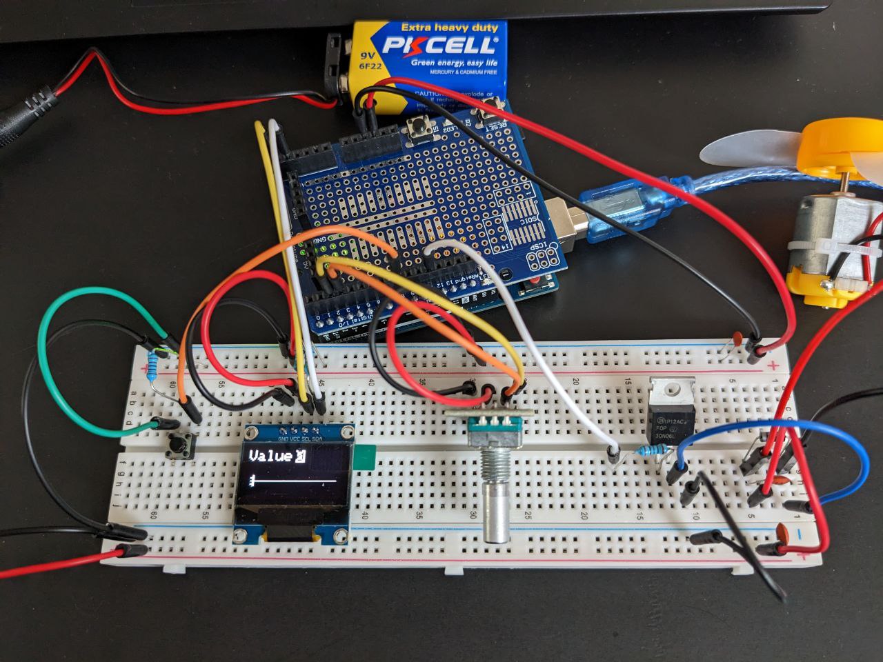
// Display content
display.print("Value: ");
// Move cursor
display.setCursor(64, 0);
// Set text to be inverted color
display.setTextColor(BLACK, WHITE);
display.println(String(currVal));
drawIndicator(currPos);
display.display();
}
}
void setup() {
// Serial.begin(115200);
// Pin 11 serves as the control pin for the MOSFET so it is set as OUTPUT
pinMode(11, OUTPUT);
// Pin 8 as the switch detect pin is set to INPUT, and when it's low it is depressed
pinMode(SW_PIN, INPUT);
myEnc.write(-KNOB_LEVEL_HALF * 4 - 2);
if(!display.begin(SSD1306_SWITCHCAPVCC, 0x3C)) {
// Serial.println(F("SSD1306 allocation failed"));
for(;;); // Don't proceed, loop forever
}
// Clear the screen
display.clearDisplay();
// Display Logo
display.drawBitmap(
(display.width() - 48) / 2,
(display.height() - 48) / 2,
epd_bitmap_images, 48, 48, 1
);
display.display();
delay(2000);
display.clearDisplay();
delay(1000);
display.setTextSize(2);
display.setTextColor(WHITE);
// Set cursor to the upper left corner
display.setCursor(0, 0);
display.print("Value: ");
// Move cursor
display.setCursor(64, 0);
// Set text to be inverted color
display.setTextColor(BLACK, WHITE);
currVal = currPos + 20;
display.println(String(currVal));
drawIndicator(currPos);
display.display();
}
void loop() {
updateInfoScreen();
swStatus = digitalRead(SW_PIN);
// The switch is active low, which means when it is depressed it becomes LOW
if (!swStatus) {
delay(50);
// Debounce here
if (!digitalRead(SW_PIN)) {
// This animation will freeze the I2C bus and the Arduino when motor is running,
// disabled it for this assignment
// drawConfirmScreen();
updateInfoScreen(true);
delay(5);
// Control the motor speed, 100 is already a decent speed for the motor
analogWrite(11, map(currPos, -20, 20, 0, 100));
delay(5);
}
}
}
int posConv(long inputPos) {
// Serial.println(inputPos);
int result;
// Result is position divided by four since the knob clicks every four turns
result = (int)(round((inputPos) / 4.0));
// Serial.println(result);
if (result > KNOB_LEVEL_HALF) {
// Knob value exceeds max value
result = KNOB_LEVEL_HALF;
// Set knob value to max to prevent further increase
myEnc.write(KNOB_LEVEL_HALF * 4 + 2);
knobExceed = 1;
}
else if (result < -KNOB_LEVEL_HALF) {
// Knob value exceeds min value
result = -KNOB_LEVEL_HALF;
// Set knob value to min to prevent further decrease
myEnc.write(-KNOB_LEVEL_HALF * 4 - 2);
knobExceed = -1;
}
else {
knobExceed = 0;
}
// Serial.println(knobExceed);
return result;
}
void drawIndicator(int inputPos) {
int _width = 2;
int _height = 16;
int _x;
int _y = 40;
int padding = 8;
// calculate indicator's position from input position value
_x = map(inputPos, -KNOB_LEVEL_HALF, KNOB_LEVEL_HALF, padding, SCREEN_WIDTH - padding);
_x = floor(_x - _width / 2);
// Draw a straight line as the slider
display.drawLine(padding, _y, SCREEN_WIDTH - padding, _y, WHITE);
// Draw a rectangle as the indicator
display.fillRoundRect(_x, floor(_y - (_height / 2)), _width, _height, 1, WHITE);
// Draw three dashes
if (knobExceed == 1) {
// Knob is turning too high
display.drawLine(SCREEN_WIDTH - padding + 2, floor(_y - _height / 4), SCREEN_WIDTH - padding + 4, floor(_y - _height / 4), WHITE);
display.drawLine(SCREEN_WIDTH - padding + 2, _y, SCREEN_WIDTH - padding + 4, _y, WHITE);
display.drawLine(SCREEN_WIDTH - padding + 2, floor(_y + _height / 4), SCREEN_WIDTH - padding + 4, floor(_y + _height / 4), WHITE);
}
else if (knobExceed == -1) {
// Knob is turning too low
display.drawLine(padding - 2, floor(_y - _height / 4), padding - 4, floor(_y - _height / 4), WHITE);
display.drawLine(padding - 2, _y, padding - 4, _y, WHITE);
display.drawLine(padding - 2, floor(_y + _height / 4), padding - 4, floor(_y + _height / 4), WHITE);
}
}
void drawConfirmScreen() {
// Clear buffer
display.clearDisplay();
// Play 20 frames of the animation
int iteration = 20;
int padding = 2;
int resultX;
int resultY;
int resultR;
// Draw a enlarging rounded rectangle here
for (int i = 0; i < iteration; i++) {
display.clearDisplay();
// Calculate W, H, and radius of the rectangle
resultX = round(easeInOutSine(i, 0, 20, 0, SCREEN_WIDTH - padding));
resultY = round(easeInOutSine(i, 0, 20, 0, SCREEN_HEIGHT - padding));
resultR = round(easeInOutSine(i, 0, 20, 0, 20));
// resultX = round(map(i, 0, 20, 0, SCREEN_WIDTH - padding));
// resultY = round(map(i, 0, 20, 0, SCREEN_HEIGHT - padding));
// resultR = round(map(i, 0, 20, 0, 20));
// Draw the rectangle
display.fillRoundRect((SCREEN_WIDTH - resultX) / 2, (SCREEN_HEIGHT - resultY) / 2, resultX, resultY, resultR, WHITE);
delay(5);
display.display();
delay(10);
}
delay(500);
// Draw a tick in the middle
display.drawBitmap((SCREEN_WIDTH - 32) / 2, (SCREEN_HEIGHT - 32) / 2, epd_bitmap_download, 32, 32, BLACK);
display.display();
delay(1500);
// Set to black screen
display.clearDisplay();
display.display();
}
// This function is similar to the built-in map() function, but with a eased curve at the start and the end of the range.
// Similar to the ease-in-out function in CSS
float easeInOutSine(int _x, int inputLow, int inputHigh, int lowerBound, int higherBound) {
int inputRange = inputHigh - inputLow - 1;
float convX = ((float)_x - (float)inputLow) / (float)inputRange;
// Serial.print(String(convX) + "; ");
int range = higherBound - lowerBound;
float result = (-(cos(PI * convX) - 1.0) / 2.0) * range + lowerBound;
// Serial.println(result);
return result;
}