The images above are my schematic for assignment 3. There are 2 LEDs, their positive nodes are connected to pin 13 and 11 of the Arduino.
Their negative nodes are connected together and connected with a 1000 ohm resistors in series. Then the resistor is connected to the ground on the Arduino board.
There's also a photocell which have one side connected to a 5V power source the Arduino, and the other side connected to pin A0 of the Arduino and a 1k resistor, which then connects to the ground.
Why 1K?
The photocell and the resistor composes of a "voltage divider", which shared the 5 volt voltage drop and both take a part of it.
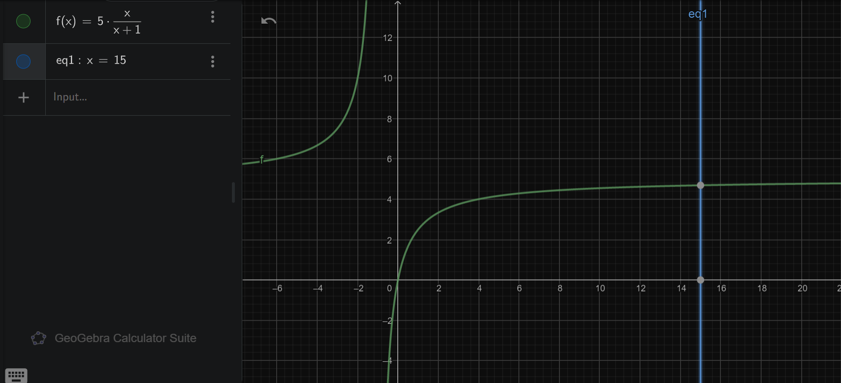
From testing with a multimeter, I found out that the photocell have a resistance ranging from ~0 to ~150k Ohms. So, to protect the arduino and to make the voltage change on the photocell large enough to be detected.
I chose a 1k resistor at the bridge. So, with a 1k resistor and a 5V power source, when the photocell have a resistance of ~0k, it has a voltage drop of ~0V; and when the photocell has a resistance of 150k Ohm,
it has a voltage drop of 5V * (150k / (150k + 1k)) = 4.97V ≈ 5V. The formula and the graph is provided below. Because we don't need the photocell to detect differences in light and stronger light,
so it's ok to have the slop flatten toward the x = 15.
Photocell and Debounce
Because the photocell reflects instant change of the ambient brightness, it can be annoying to see the Arduino triggered just by a leaf falling down. To make it detect only changes that lasts for a period of time (e.g. 200ms). We will have to "debounce" the photocell.
The logic is simple: we store the previous state of the photocell, and when the current state is different than the previous state, we wait for a while and check again. If the state is still different, we treat it as a new state and act accordingly.
An example code snippet for debounce is provided below:
Serial.println("Reading Pin A0...");
pinA0Val = map(analogRead(A0), 0, 1023, 0, 255);
Serial.println("Pin A0 reads: " + String(pinA0Val));
pinA0State = (pinA0Val < DARK_THRESHOLD);
if (pinA0State != pinA0StatePrev)
{
    delay(1000);
    pinA0State = (map(analogRead(A0), 0, 1023, 0, 255) < DARK_THRESHOLD);
    Serial.println("Pin A0 reads: " + String(pinA0Val));
    if (pinA0State != pinA0StatePrev) {
        pinA0StatePrev = pinA0State;
    }
    else {
        pinA0State = pinA0StatePrev;
    }
}
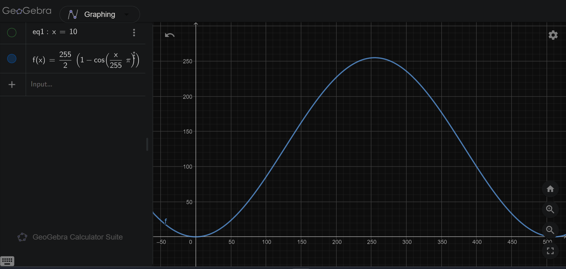
When testing the code, I found that the value of analogWrite is not a linear relationship with the brightness of the LED. When analogWrite increases constantly, the LED's brightness would grow fast at first and then slow down.
Using the functions in the Arduino library, I developed a function that can produce a shifted cosine wave that have an input field and a output field both from 0 to 255. The screenshot below shows the graph of the function.
f(x) = 255 / 2 * (1 - cos(x * PI / 255))
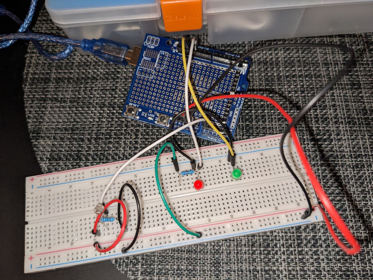
Circuit
Above the blueprint
The above image shows the actual Arduino circuit build on breadboard.
Firmware
Inside the chips
bool pinA0State;
bool pinA0StatePrev;
int pinA0Val = 0;
int pin11Val = 0;
int DARK_THRESHOLD = 10;

void setup() {
    pinMode(13, OUTPUT);
    pinMode(11, OUTPUT);
    Serial.begin(115200);
}

void loop() {
    // put your main code here, to run repeatedly:
    //Print out status to the serial port
    Serial.println("Reading Pin A0...");
    //Read the voltage from pin A0, and convert the value range from 0-1023 to 0-255 (better fit output value)
    pinA0Val = map(analogRead(A0), 0, 1023, 0, 255);

    Serial.println("Pin A0 reads: " + String(pinA0Val));

    //Set pinA0State to TRUE if pin A0 reads below 30, FALSE otherwise.
    pinA0State = (pinA0Val < DARK_THRESHOLD);

    //If pinA0 has a different state as the stored, previous one
    if (pinA0State != pinA0StatePrev)
    {
        //Wait 1 second to debounce
        delay(1000);
        //Read pin A0 again, and do the 0-1023 to 0-255 conversion again
        pinA0State = (map(analogRead(A0), 0, 1023, 0, 255) < DARK_THRESHOLD);
        Serial.println("Pin A0 reads: " + String(pinA0Val));
        //If state is still different than the previous one, use the current state as the new state
        if (pinA0State != pinA0StatePrev) {
            pinA0StatePrev = pinA0State;
        }
        //Use the previous state otherwise
        else {
            pinA0State = pinA0StatePrev;
        }
    }

    //Turn LED at pin 13 on
    digitalWrite(13, pinA0State);

    //If pinA0State is TRUE and pin11Val is not max, increase pin11Val
    if (pinA0State && pin11Val < 255) {
        pin11Val++;
    }
    //If pinA0State is FALSE and pin11Val is higher than 0, decrease pin11Val
    else if (pin11Val > 0) {
        pin11Val -= 5;
    }

    //Because Arduino cannot write negative value, we set pin11Val to 0 is it's negative
    if (pin11Val < 0) {
        pin11Val = 0;
    }

    //A small equation to smooth the lighting curve, graph on website
    int pin11Conv = (255 / 2) * (1 - cos(pin11Val * PI / 255));
    //Print out pin11Conv to the serial port
    Serial.println("pin11 original value: " + String(pin11Val));
    //Write pin11Conv's value to port 11's LED
    analogWrite(11, pin11Conv);
    //Print out pin11Val to the serial port
    Serial.println("pin11 converted value" + String(pin11Conv));

    delay(500);
}
Actual Operation
Coming alive
The above gif shows how this program runs. There are two LEDs, LED 13 and LED 11.
-
LED 13 (green LED) acts as a photocell indicator, it turns on when the photocell is covered for at least one second and turns off when it's uncovered for at least one second.
-
LED 11 (red LED) gradually lights up when the photocell is covered, and goes out quickly when the photocell is uncovered.
Example Serial Output
Reading Pin A0...
Pin A0 reads: 31
pin11 original value: 0
pin11 converted value0
Reading Pin A0...
Pin A0 reads: 31
pin11 original value: 0
pin11 converted value0
Reading Pin A0...
Pin A0 reads: 31
pin11 original value: 0
pin11 converted value0
Reading Pin A0...
Pin A0 reads: 31
pin11 original value: 0
pin11 converted value0
Reading Pin A0...
Pin A0 reads: 31
pin11 original value: 0
pin11 converted value0
Reading Pin A0...
Pin A0 reads: 31
pin11 original value: 0
pin11 converted value0
Reading Pin A0...
Pin A0 reads: 31
pin11 original value: 0
pin11 converted value0
Reading Pin A0...
Pin A0 reads: 31
pin11 original value: 0
pin11 converted value0
Reading Pin A0...
Pin A0 reads: 31
pin11 original value: 0
pin11 converted value0
Reading Pin A0...
Pin A0 reads: 31
pin11 original value: 0
pin11 converted value0
Reading Pin A0...
Pin A0 reads: 31
pin11 original value: 0
pin11 converted value0
Reading Pin A0...
Pin A0 reads: 31
pin11 original value: 0
pin11 converted value0
Reading Pin A0...
Pin A0 reads: 30
pin11 original value: 0
pin11 converted value0
Reading Pin A0...
Pin A0 reads: 30
pin11 original value: 0
pin11 converted value0
Reading Pin A0...
Pin A0 reads: 7
Pin A0 reads: 7
pin11 original value: 1
pin11 converted value0
Reading Pin A0...
Pin A0 reads: 8
pin11 original value: 2
pin11 converted value0
Reading Pin A0...
Pin A0 reads: 8
pin11 original value: 3
pin11 converted value0
Reading Pin A0...
Pin A0 reads: 8
pin11 original value: 4
pin11 converted value0
Reading Pin A0...
Pin A0 reads: 7
pin11 original value: 5
pin11 converted value0
Reading Pin A0...
Pin A0 reads: 7
pin11 original value: 6
pin11 converted value0
Reading Pin A0...
Pin A0 reads: 8
pin11 original value: 7
pin11 converted value0
Reading Pin A0...
Pin A0 reads: 8
pin11 original value: 8
pin11 converted value0
Reading Pin A0...
Pin A0 reads: 7
pin11 original value: 9
pin11 converted value0
Reading Pin A0...
Pin A0 reads: 8
pin11 original value: 10
pin11 converted value0
Reading Pin A0...
Pin A0 reads: 8
pin11 original value: 11
pin11 converted value1
Reading Pin A0...
Pin A0 reads: 8
pin11 original value: 12
pin11 converted value1
Reading Pin A0...
Pin A0 reads: 8
pin11 original value: 13
pin11 converted value1
Reading Pin A0...
Pin A0 reads: 8
pin11 original value: 14
pin11 converted value1
Reading Pin A0...
Pin A0 reads: 8
pin11 original value: 15
pin11 converted value2
Reading Pin A0...
Pin A0 reads: 8
pin11 original value: 16
pin11 converted value2
Reading Pin A0...
Pin A0 reads: 8
pin11 original value: 17
pin11 converted value2
Reading Pin A0...
Pin A0 reads: 7
pin11 original value: 18
pin11 converted value3
Reading Pin A0...
Pin A0 reads: 7
pin11 original value: 19
pin11 converted value3
Reading Pin A0...
Pin A0 reads: 8
pin11 original value: 20
pin11 converted value3
Reading Pin A0...
Pin A0 reads: 8
pin11 original value: 21
pin11 converted value4
Reading Pin A0...
Pin A0 reads: 8
pin11 original value: 22
pin11 converted value4
Reading Pin A0...
Pin A0 reads: 7
pin11 original value: 23
pin11 converted value5
Reading Pin A0...
Pin A0 reads: 8
pin11 original value: 24
pin11 converted value5
Reading Pin A0...
Pin A0 reads: 31
Pin A0 reads: 31
pin11 original value: 19
pin11 converted value3
Reading Pin A0...
Pin A0 reads: 33
pin11 original value: 14
pin11 converted value1
Reading Pin A0...
Pin A0 reads: 33
pin11 original value: 9
pin11 converted value0
Reading Pin A0...
Pin A0 reads: 33
pin11 original value: 4
pin11 converted value0
Reading Pin A0...
Pin A0 reads: 33
pin11 original value: 0
pin11 converted value0